
 LinkT&B Editorial Department
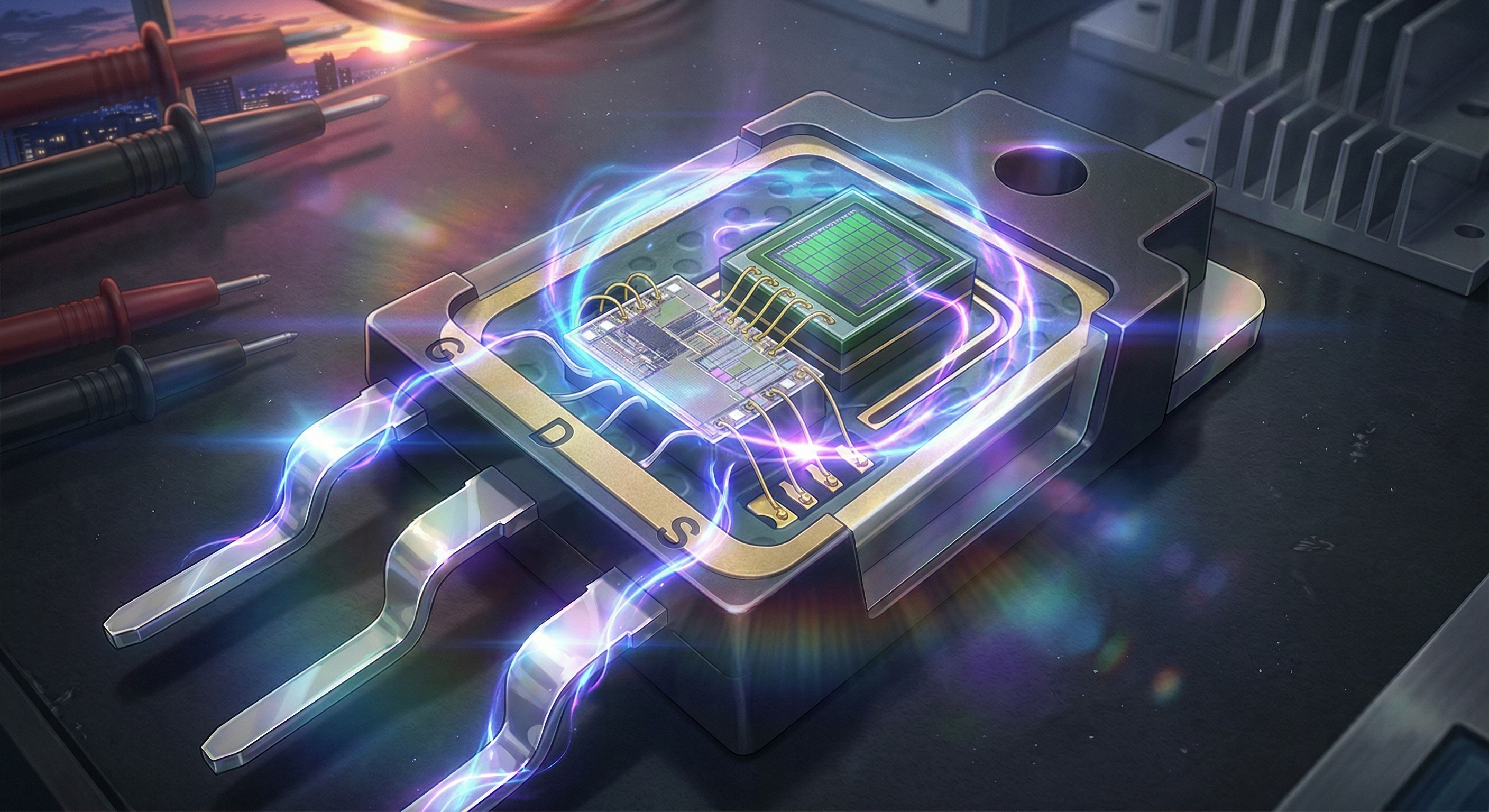
The value of a SiC MOSFET is not determined by voltage rating or on-resistance alone. Compare switching losses, gate drive, layout and cooling with silicon or IGBT alternatives at the intended voltage, current and temperature.
Contents
Comparing candidate devices consistently
| Item | What to check | How to assess it |
|---|---|---|
| Conduction | Current, junction temperature and gate voltage | Check hot-state losses |
| Switching | Voltage, current, frequency and gate resistance | Evaluate losses and noise together |
| Protection | Short circuit, surge and false turn-on | Coordinate datasheet limits and protection timing |
| Procurement | Package, supply and evaluation support | Device and supporting-circuit cost |
Define the loss you want to reduce
Silicon-carbide MOSFETs are candidates for reducing switching losses and size in high-voltage power converters. Replacing silicon does not guarantee better efficiency. Compare conduction loss, switching loss, gate drive, surrounding components and cooling at the same operating point.
Read new-generation claims with their test conditions
ROHM announced completion of its fifth-generation SiC MOSFET development on 21 April 2026. Performance comparisons require the previous generation, die area, junction temperature and package conditions. Announcement, sampling and volume availability are different milestones; confirm the selected part’s datasheet and supply status. ROHM announcement.
Faster switching increases sensitivity to layout
Reduced switching losses can be accompanied by voltage overshoot, gate ringing and common-mode noise. Design the power loop, gate return and driver placement together rather than changing only the gate resistor.
False turn-on and short-circuit protection depend on more than threshold voltage. Check driver current, supply voltage, isolation and response time against the device requirements. Negative turn-off voltage is not universally required. Infineon design recommendations.
There is no universal frequency boundary between Si and SiC
A rule such as “SiC above 100 kHz, silicon below” is not reliable. Voltage, current, topology, soft switching, reverse conduction and temperature affect the comparison.
Estimate losses from datasheets, then validate representative voltage and current conditions, for example with double-pulse testing. Measure complete-converter efficiency, temperature and noise before claiming that magnetics or cooling hardware can be reduced. A higher device price may or may not be offset elsewhere.
Plan for production and abnormal operation
Check component variation, gate-drive margins, overload, cooling faults and start-up or shutdown. A substitute with similar voltage and on-resistance is not automatically interchangeable: gate charge, capacitances and protection requirements can differ.
LinkT&B supports power-stage design, layout and prototype evaluation. Supply voltage, load current, cooling arrangements and troublesome waveforms help define an appropriate test programme.
Discuss your project
We support circuit design, prototyping and hardware testing. Tell us about the operating conditions and the problem you need to investigate.